Electronics in general is my bailiwick, and that includes processing equipment and controls, TV transmitters, microphones, sync generators, amplifiers, microwave systems, . . .
Full Wave Bridge Rectifier (FWBR)
A Full Wave Bridge Rectifier is made up of four standard, rectifying, silicon diodes inside a single package. Because they're in a single box, they're easier to install in the equipment by the manufacturer, and easier to replace as a single package. However, a FWBR is still four, single diodes inside a single box.
Keep in mind, any standard rectifying silicon diode conducts electrical current one direction, but not the other.
To come up with the rectification needed, I've gone so far as to make my own FWBRs out of four single diodes. The four diodes, rather than in a single package like a Full Wave Bridge Rectifier, are also separate on quite a few fire alarm power supplies, or on other power supplies. Some manufacturers use four diodes in a bridge configuration, some manufacturers use Full Wave Bridge Rectifiers.
When the four single rectifying diodes are wired exactly the way that the diode package labeled FWBR is wired, the four diodes
are a Full Wave Bridge Rectifier.
Common Wiring for a Full Wave Bridge Rectifier
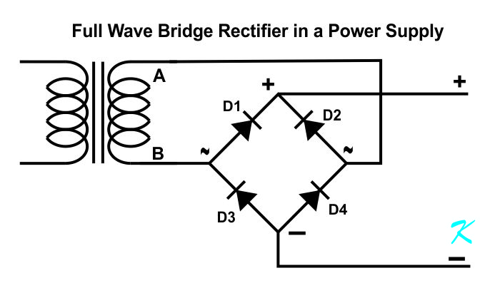
When we look at a Full Wave Bridge Rectifier, we are looking at some diodes used to rectify the full wave of the AC signal, coming on the AC input. The word "Rectifier", in this case, means diode or diodes. The words "Full Wave" means the entire AC signal, and the word "Bridge" shows the configuration for the diodes.
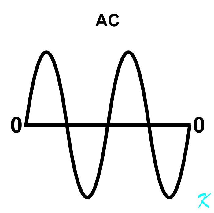
In the Common Wiring diagram, above, the input to a Full Wave Bridge Rectifier is a pure AC sine wave.
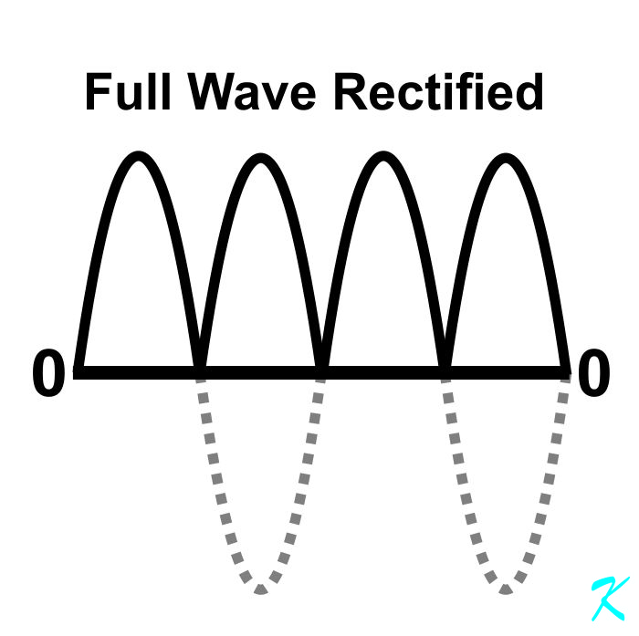
The output of a Full Wave Bridge Rectifier is still the full wave of the AC signal, but the positive half of the cycle will provide a positive voltage, and the negative half of the AC signal will also provide a positive voltage.
Another way of looking at it is that each of the half-waves of AC on the input of a full wave rectifier produces a positive going pulse. Each pulse goes from zero volts, to full voltage, to zero volts again.
There are two positively going pulses for each single cycle of AC. Because there are two pulses for each cycle of AC, and the AC is running at a rate of 60 cycles a second (in the U S), the pulse rate is 120 times a second, or 120 Hz Pulsed DC.
Theory
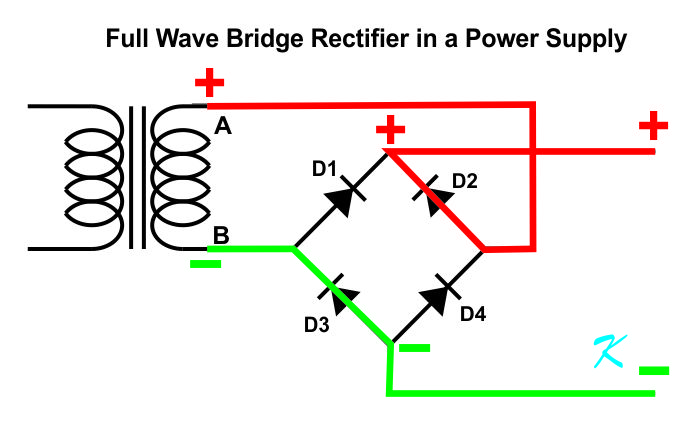
When the transformer is positive on A and negative on B, diodes D2 and D3 are conducting, making the output positive.
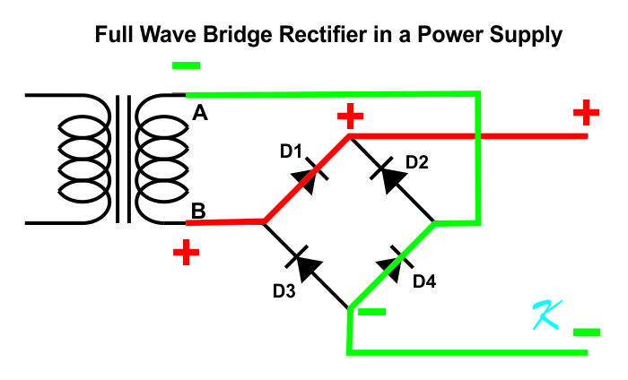
When the transformer is negative on A and positive on B, diodes D1 and D4 are conducting, making the output positive.
No matter what the voltage is on the output of the transformer, the voltage on the output of the Full Wave Bridge Rectifier is going to be positive.
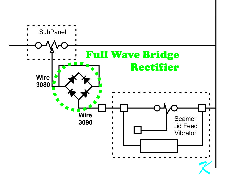
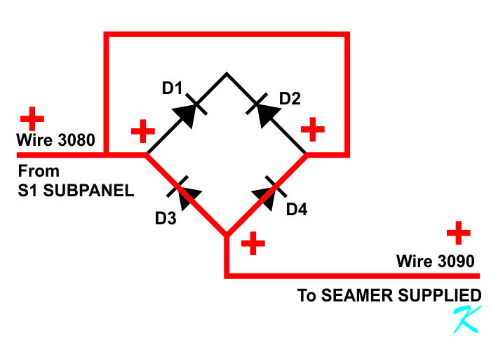
Your FWBR Assembly
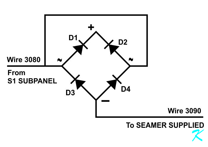
This assembly does look to be a bit confusing. When I get confused, I redraw. That way, I can understand it my way.
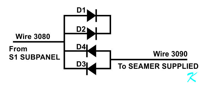
This is the exact same circuit, but redrawn. Remember, a Full Wave Bridge Rectifier is just four diodes in the same package.
- The anodes of D1 and D2, and the cathodes of D4 and D3 are all connected to wire 3080.
- The cathodes of D1 and D2 are connected to each other, but to nothing else. D1 and D2 are useless.
- The anodes of D4 and D3 are both connected to wire 3090. D4 and D3 are connected in parallel.
This is the signal coming in on wire 3080.
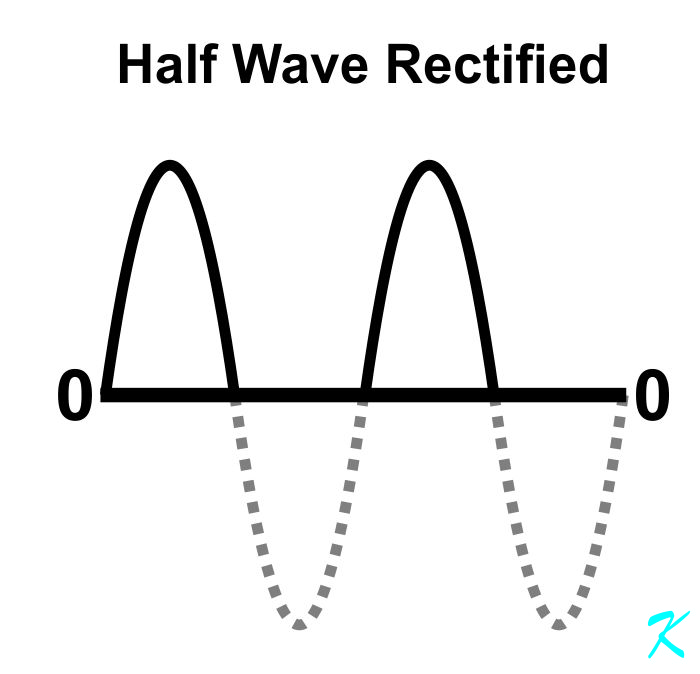
This is what is coming out of the diode assembly on wire 3090.
Another way of looking at it is that each positve cycle of AC on the input of a half wave rectifier produces a positive pulse, while each negative pulse of AC doesn't produce any pulse.
There is a single positively going pulse for each single cycle of AC (in the U S). Because there is only one pulse for each cycle of AC, the pulse rate is 60 times a second, or 60 Hz Pulsed DC.
Theory
For theoretical purposes, D4 and D3, being in parallel, are a single diode. The package of diodes may say "Full Wave Bridge Rectifier", but the package is being used as a "Half Wave Rectifier".
A single diode, as it is used in the SEAMER LID FEED VIBRATOR, is a Half Wave Rectifier.
When the signal on wire 3080 is positive, the diode pair (D4 and D3) will be conducting.
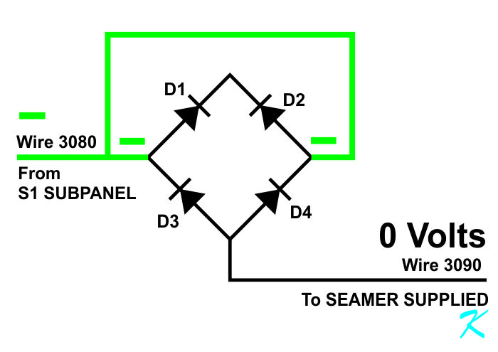
When the signal on wire 3080 is negative, the diode pair will not be conducting.
The rectifier assembly is only letting half of the AC wave through.
The Role of the Full Wave Bridge Rectifier
The role of the rectifier package, as it is used in the processing equipment, is to prevent the negative half of the AC signal from passing through, while allowing the positive half of the AC signal to continue on to power the SEEMER LID FEED VIBRATOR.
60 Hz Vibration Rate
Now, it could be that the vibrator is just a big electromagnet that shakes the SEAMER LID FEED VIBRATOR at the 60 Hz power line frequency. I can't tell for sure without being there. That is that is one possible reason for a Half Wave Rectification.
How Is the FWBR Used?
The whole assembly, from the variable voltage feed on wire 3080, through the halfwave rectification, and on to the vibrator on wire 3090 is a is a half-wave rectification assembly.
The actual signal looks like this on an oscilloscope.
I'm not sure how the vibrator uses the signal (Power is a Signal), but it's the vibrator that determines why the signal is half of an AC signal.
I hope, though, that this will help you understand more of the system you're maintaining.
Douglas Krantz