I cannot find datasheet on the web for a Honeywell Module FRM-1. You will have to contact Honeywell Technical Support to get a datasheet.
The PAM-1 relay, though, is a very common relay that's used in fire alarm systems. You can get a datasheet at:
https://cgproducts.johnsoncontrols.com/cat_pdf/PAM-1.pdf
Fire Alarm Control Relay Specifications
The reason for having two relays in the first place is that the fire alarm's control relay has really tiny contacts. They can't handle much of anything, especially door holders.
Shown on the Installation Sheets that come inside the package with the relay, the specifications for the fire alarm control relay contacts say something like, non-inductive, non-capacitive, low reactance, or . . . pilot duty. As a rule of thumb, the fire alarm's control relay can only switch on and off small relay or a 24-volt lightbulb, but not something like a motor, a door holder, a door strike, or anything else inductive. Some of the relays will internally weld their contacts together after 20 or so operations, that is with some electrical universal-voltage relays. Read the specification of the fire alarm's control relay very carefully.
OK. Most fire alarm control relays say they are rated to switch 2.0 Amps at 24 Volts, or 0.5 Amps at 120 Volts. If as a footnote, they include that the relays can only switch non-inductive, non-capacitive, low reactance, or only to be used on pilot duty circuits, never be directly connect a door holder, a door strike, or anything else inductive.
Directly connecting the inductive devices will only mean that later, the fire alarm control relay will have to be replaced, and replaced, and replaced.
Diagrams
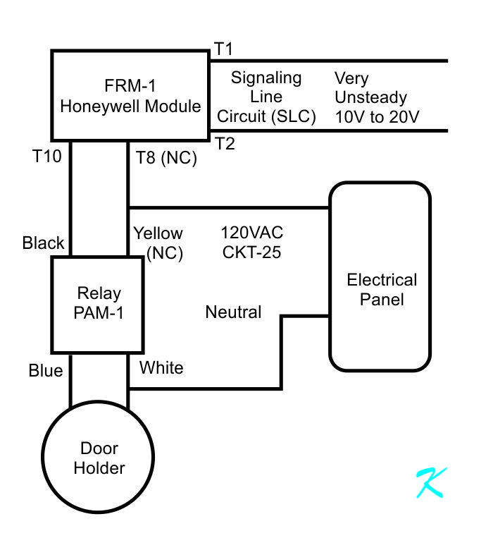
I've taken the liberty of redrawing your diagram, showing the pathways of the electrical current.
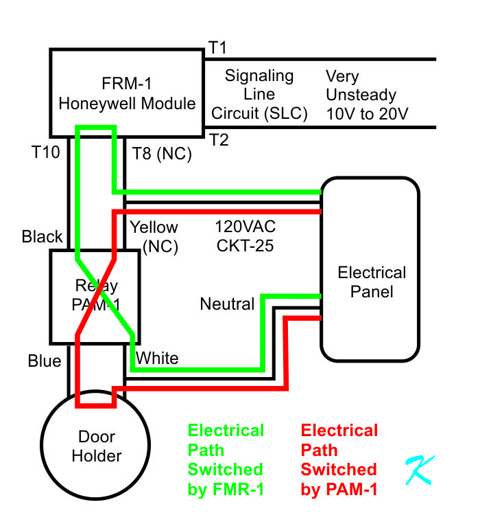
The green pathway electricity is turned on and off by the relay inside the FRM-1. The PAM-1 relay is operated by this current.
The red pathway electricity is turned on and off by the relay onside the PAM-1. The door holder is operated by this current.
Relays Inside the FRM-1 and the PAM-1
Inside the Honeywell Module, and inside the PAM-1 relay module, is a standard electrical relay. These relays come in different sizes and shapes, and some have a protective box around them. They all, however, use the same basic diagram.
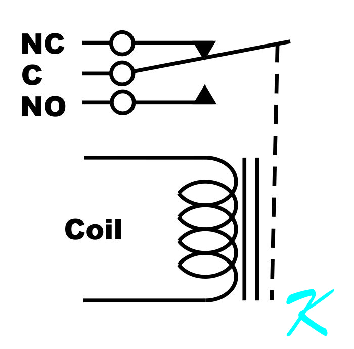
This is the schematic of the relay that's inside the modules. Often, relays are used to electrically isolate the input (the coil) from the output (the contacts). Sometimes, relays are used so that a small voltage or current on the coil will switch a much larger voltage or current.
Used in electrical systems, some high-power relays are called contactors. A contactor is a relay with a "Contactor" label stamped on its side rather than "Relay" label. It also looks a lot bigger than a relay on a circuit board.
On the schematic above, notice the dotted line between the relay's coil and the contacts. The dotted line represents magnetism; there isn't an electrical connection between the relay coil and the relay contacts.
Many relays have more than one set of contacts, and each set of contacts are electrically separated from the others. The idea, though, is that, like a switch-on-the-wall operated by someone's hand, a single coil operates all the contacts in the relay at once.
See:
https://www.douglaskrantz.com/ElecHowDoesARelayWork.html for more information on the internal relay itself.
Redrawing the Wiring Diagram
Wiring diagrams, like the one you set, are great for knowing which wire goes to which screw terminal or other wire. When installing a designed circuit, it's easier to follow a wiring diagram rather than a design and maintenance schematic.
When looking at a circuit, either to design it or to find troubles with it, I have to redraw the circuit to follow signal flow.
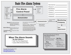
Block Diagram
The first step is understanding a circuit is to create a block diagram of the circuit.
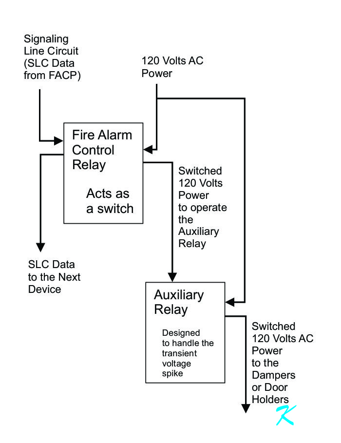
Here, the Fire Alarm Control Relay (FRM-1 Honeywell Module) receives a command over the SLC data loop, turning the relay inside the module on and off. The relay inside the module is used to switch on and off the power needed to activate the Auxiliary Relay (PAM-1 Relay).
The Auxiliary Relay then turns on and off the power to the door holders.
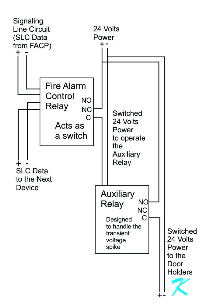
Schematic Diagram
This is a very similar diagram to the diagram you sent me. Mostly, the diagram is just redrawn.
In order to understand the need for the Auxiliary Relay, see:
https://www.douglaskrantz.com/Blogdoorholderrelay.html
Theory of Operation
Normally, when there no alarm, the Fire Alarm Control Relay (FRM-1) is providing power to the Auxiliary Relay (PAM-1). The Auxiliary Relay then provides power to the door holder.
When doors are supposed to close, the Fire Alarm Control Panel uses data on the Signaling Line Circuit (SLC) to tell the Control Relay (FRM-1) to go into its fire alarm mode, which activates its internal relay to switch off the current to the Auxiliary Relay (PAM-1).
The Auxiliary Relay then turns off, so its internal relay shuts off power to the door holder.
It's only when the Fire Alarm Control Panel uses data to tell the Fire Alarm Control Relay (FRM-1) to go back to normal, that the that the Auxiliary Relay can turn on again and provide power to the door holder.
Looking for Visual Damage
The problem you're noticing is that when some smoke detectors go into alarm, some of the door holders are not turning off (Floors 2 to 5). Some of the door holders are still receiving electricity even when there is a fire alarm.
In order to turn off the current, the electrical path has to be broken. A wire breaking, a wire coming out of a screw or wire nut connector, or the contacts opening up inside a switch or relay will stop the current.
The wires are conducting electricity, and the screw connections and wire nut connectors are also conducting electricity. That is what they are supposed to do.
On the other hand, the relays inside the FRM-1 and the PAM-1 modules are not stopping the current when some smoke detectors go into alarm. Because the relays inside the FRM-1 and the PAM-1 modules are inside plastic boxes, the mechanics of the relays can't be visually inspected.
We have to look at these relays from a different point of view. For the FMR-1 relay to fail to turn off, either the particular FMR-1 module did not receive the turn-off command from the fire alarm control panel, or the contacts in the relay are welded together.
For the PAM-1 relay to fail to turn off, either the PAM-1 relay module is still receiving electricity from the FMR-1 relay, or the contacts of the relay inside the PAM-1 module are welded together.
Of the thousands of relays I've worked with over 40 years, I've seen only a couple of relays that had their contacts welded together. A much greater possibility is that the fire alarm control panel isn't sending the commands to change state to the FMR-1s.
Troubleshooting
The first thing to try is to set the smoke detectors next to the fire doors in question into alarm. When the smoke detectors next to the fire doors go into alarm, and if the doors next to the smoke detectors in alarm close, the wires and relays associated with the door holders are good.
WARNING: Setting the smoke detectors into alarm in the elevator lobbies will capture the elevators, making the elevators totally unusable until a reset key, provided by the elevator company, is used.
WARNING: The fire department will be called when setting the smoke detectors into alarm. Also, the all the fire horns in the whole building will make a lot of noise.
Remember, the door holders are part of the building-wide fire alarm system. It could be that the door holders are acting the way the fire marshal and elevator inspector require; it could be that the door holders and their related circuity, or even the programming in the fire alarm control panel, are having problems.
Before trying to change anything, check to make sure you know how the door holders are supposed to work.
Douglas Krantz
 By Douglas Krantz |
Maintenance
By Douglas Krantz |
Maintenance