Not Normal
No. This does not sound normal.
Before changing anything on the fire alarm system, though, the whole "what's going on with the wiring" needs to be researched. In other words, the system works now, don't change it unless you are absolutely sure you need to.
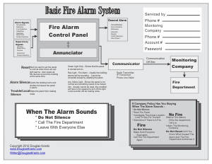
Remember, as it is right now, the whole building-wide fire alarm system has been certified by the fire marshal to detect fires and warn people, and also shut down the air handler when there's a fire. Changing the wiring may mean that the system has to be recertified.
Life-Safety
The following discussion is based on the life-safety's idea that nothing should ever interfere with a fire alarm system's ability to "Detect Fire and Warn People". As an example, that's why there are backup batteries; so that even when there's a utility company's power failure, the fire alarm system will stay powered-up and active.
Also, based on the same life-safety's idea, all equipment and devices connected directly to a fire alarm system has to be be "Listed for Use in a Fire Alarm System", and all equipment has to be "Compatible".
I know. "Listed" and "Compatible" are legal-ease terms, but the legal-ease terms have real-life concerns.
Real Electrical Compatibility
Listed for Use in a Fire Alarm System is the first step in the process. It means that the equipment has been tested, and confirmed to work in a fire alarm system by a third party, nationally known testing laboratory, like UL, ULC, FM, CE, CCC, etc. The listing part is where the testing laboratory has placed what was tested on their list of equipment and devices that work in a fire alarm system.
If it isn't listed, no one knows for sure whether the equipment or device will work at all, work sometimes, give false results, or actually work all the time.
Compatible goes one step further. Compatible means that two or more pieces of equipment will work together.
If the combination isn't compatible, no one knows for sure that in a fire alarm system, whether the equipment or device will work together at all, maybe only work together sometimes, give false results, or actually work all the time.
In other words, the legal-ease wording is based on making sure that electronically, the fire alarm system will always work to detect fire and warn people.
The Fire Alarm System is Stand-Alone
A fire alarm system is supposed to be totally electrically and electronically isolated from anything else, unless, of course, the fire alarm system has specifically been tested and listed as being compatible with what's connected to it.
On conventional systems, switches are usually compatible with the Initiating Device Circuit (IDC - input loop). How the switches should be wired is shown in the installation manual that comes with the panel.
24-Volt Power Supply
The 24-volt auxiliary power supply in the fire alarm panel is designed to provide power to devices outside the panel. Providing that the current-capacity for the power supply isn't exceeded, the power supply may be used to power:
- Door holders
- Door locks
- 4-wire smoke detectors connected to the fire alarm system
- 4-wire duct detectors connected to the fire alarm system
- Relay coils for relays used to control other equipment
No voltage should ever be back-fed into the fire alarm system's auxiliary power supply.
Relays
Relays are commonly used in fire alarm systems to electrically isolate the fire alarm system from devices that are being controlled by the fire alarm system. The relays are really switches that use an electromagnet (coil) to turn on and off.
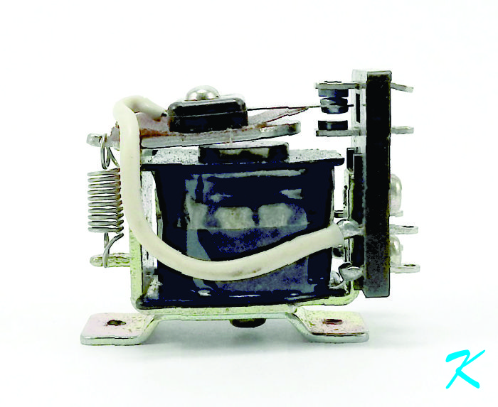
This is a picture of a commonly used relay. While electrically separated from the contacts, the coil moves the Common (C) contact between the Normally Closed (NC) contact and the Normally Open (NO) contact.
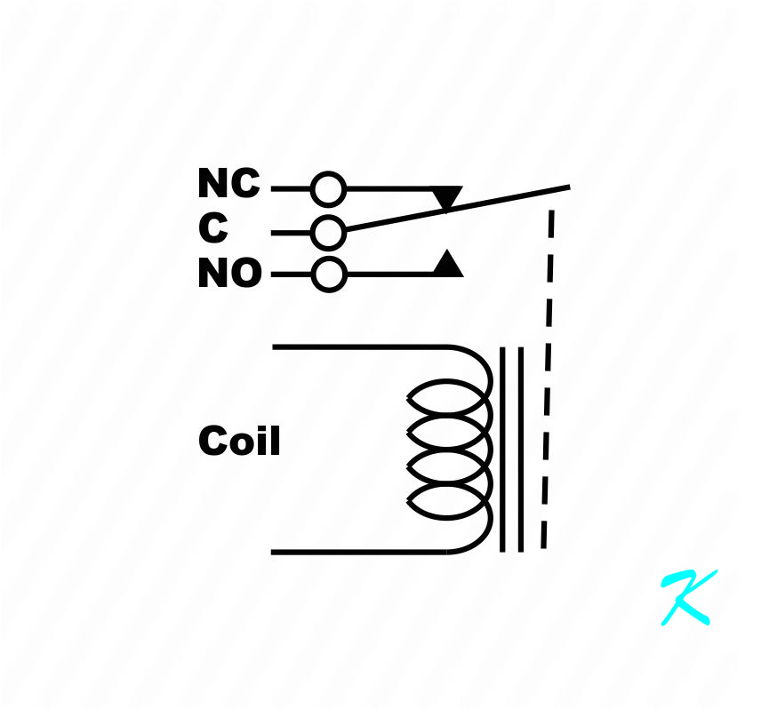
Fire alarm systems use relays to isolate the fire alarm system from other electrical or electronic equipment; using only magnetism, the coil controls the position of the Common (C) contacts. There is no electrical connection between the coil and the contacts.
To get a good idea of exactly how a relay works, see:
https://www.douglaskrantz.com/ElecHowDoesARelayWork.html https://www.douglaskrantz.com/ElecHowDoesARelayWork.html
Troubleshooting
Sometimes, while troubleshooting a system, rather than thinking about what I have done, like "Set the panel into alarm" or "Press Reset", I have to think about what the panel is doing, like "When the panel is in alarm" or "When the panel is normal".
Yeah, I know that it sounds like I'm mincing words. However, at least in this case, rather than looking at what the panel is doing at the time I press buttons, I'm looking at what happens to the rest of the system when the panel is in certain conditions. My pressing buttons isn't important; it's what the panel is doing to the wires leaving the panel that's important.
Redraw Wiring
When I don't properly understand a circuit, I've found that re-drawing the circuit helps. Redrawing the circuit helps me to understand where the current is flowing, and what causes the current to change.
I'm taking a guess on this.
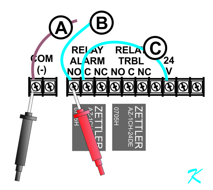
This is a simplified view of the connections on the panel you showed me. These are the wires in question, and this is also showing where the voltage measurements are being taken on the terminal strip.
To help with the following discussion, the wires have the A, B, and C labels.
Even though it looks somewhat different, the drawing is exactly that same as the original drawing, even the voltmeter probes are electrically in the same place.
Before going further, though, notice that there are two sources of power: a 24-volt power source and an 8-volt power source.
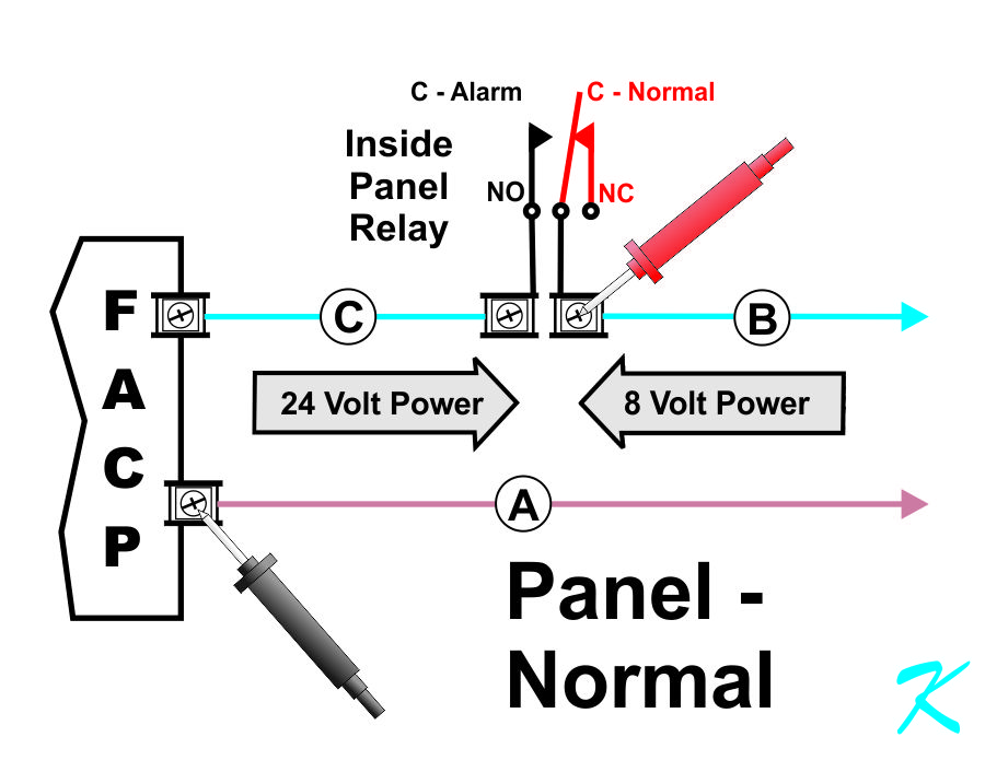
The voltage that's measured across the probes is the 8 volts you mention in your question. When the panel is normal, not in alarm, note the position of the relay contacts; the Common contact (C) connects to the Normally Closed (NC) contact. In essence, the relay contacts, acting as a switch, don't allow current to flow between the two power sources.
This drawing is the same, even the meter probes are in the same place.
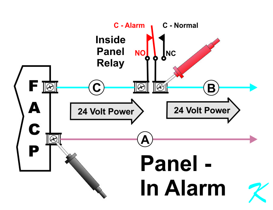
The voltage that's measured across the probes is the 24 volts you mention in your question. When panel is in alarm, the Common contact connects (C) to the Normally Open contact (NO). In essence, the relay contacts, being used as a switch, allows current to freely flow directly between the two power sources.
The wires (A) and (B) go out of the panel, but the circuitry that they attach to outside the panel is unclear. What we can deduce, though, is that the 8-volt power source is very weak compared to the 24-volt power source because the 24-volt power source overrides and takes over the 8-volt source.
Normal?
Is this hook-up normal? What is really being done is that the 8-volt power source is forced to lock-step to 24 volts when there's an alarm. The fire alarm panel and the air handler may work together for now, but in the future, if there's any changes made to either system, the two systems may have compatibility issues and no longer work together, and possibly damage each other.
Douglas Krantz