To learn more about what a non-linear resistor is, read the article at:
Is Water a Non-Linear Resistor?
Ohmmeter
An ohmmeter is actually a current meter. It has an internal battery, usually 3 volts or 9 volts, to drive the current. For the display, an ohmmeter divides the internal battery voltage by the current (it uses Ohm's Law).
The result that's displayed is the resistance, in ohms.
Ground Fault Detector
A ground fault detector is an ohmmeter. The only difference is the extra 36 volts of battery voltage, and a resistor, added in series to one of the test leads.
To build a ground fault detector for use on fire alarm systems, use the instructions published in the Nuts and Volts Magazine September 2010 Issue, Page 42 at:
Build a Low Voltage Insulation Tester https://nutsvolts.texterity.com/nutsvolts/201009/?folio=42&pg=42#pg42
When calling up that site, just by X-ing out of the subscription request drop-down, you can read most of the article. However, even if you're cheap like me, you still might want to subscribe. The subscription isn't all that expensive, it's a good magazine for the electronic hobbyist, and besides, you can read the full article.
The advantage to building your own detector is that you learn more about soft ground faults, and more about the testing for soft ground faults. Not only that, but without spending much money on the detector, you can possess a very useful test instrument.
The disadvantage is that it really is a one-person test meter. It will never be an industrial strength meter to be shared with other technicians around the shop; unlike most store-bought meters, it won't stand up to abuse.
Depending on how you look at it, an advantage or disadvantage is that the display on the homemade ground fault detector is not calibrated at all. All you can see is that the meter's needle doesn't move, barely moves when testing, moves a little, or moves a lot. If the needle doesn't move, it's measuring an open circuit. If the needle moves a lot, it's measuring low resistance. How you interpret the in-between measurements are up to your judgment. After playing with the meter for a while, you'll get used to what you see.
Insulation Tester
More than a dozen manufacturers make and sell insulation testers. They're used to test the insulation on wires. Ground faults are a failure of the insulation, and a common instrument to test the insulation breakdown is an insulation tester.
An insulation tester is an ohmmeter. One difference is that the insulation tester's display doesn't use Ohm's Law, the display only shows current.
The other difference is in safety for the fire alarm system devices. Commercial insulation testers have various battery voltages, some of them have battery voltage as high as 15,000 volts. At the time I wrote the Nuts and Volts article, the lowest internal battery voltage for an off-the-shelf insulation tester was 100 volts.
That 100-volts is just fine when only insulated wire is involved. Fire alarm systems, though, have devices attached to the wires. That 100-volts is more voltage than I want to use on any electronic device.
Since the time the article was published, insulation testers that were switchable from 10 volts to 100 volts became available. Personally, I might not remember to check the switch each time I use it, and might leave it at the 100-volt setting. So that I can't make a mistake working on a life-safety fire alarm system, a ground fault detector that can't ever go above 40 volts is my choice.
Using an Ohmmeter, a Ground Fault Detector, or an Insulation Tester
Electrically, there is no difference between an ohmmeter, a ground fault detector, or an insulation tester. All of them are current measurers. In theory, the actual schematic for each of these can be exactly the same. Yes, with digital electronics, all of them are different, but when using mechanical meter movements instead of digital displays, the schematics for all three are almost identical.
The battery voltage is different on each type of device:
- The ohmmeters use batteries anywhere from 1.5 volts to 9 volts
- The ground fault meter uses about 18 volts to 36 volts
- The insulation tester uses 10 volts to 15,000 volts
The display is different on each type of device:
- The ohmmeter has a calibrated resistance display
- The ground fault detector has an un-calibrated resistance display
- The insulation tester has a calibrated current display
When looking for ground faults, the three types of instruments are used in exactly the same way. They are used to detect leaking current, caused by low resistance between the wires and ground.
Surge Suppressor
A surge suppressor is a non-linear device: it has a voltage knee. Below that knee voltage, the surge suppressor does not conduct any electricity, it has close to infinite resistance. As the voltage is increased above the knee voltage, the surge suppressor starts to conduct, but doesn't short out, as such. The surge suppressor only conducts enough current to keep the voltage down to that knee voltage.
A Zener diode works much the same way, below it's knee voltage, it doesn't conduct, above the knee voltage the Zener diode conducts enough current to keep the voltage down close to the knee voltage.
One difference between a Zener diode and a surge suppressor is the Zener will only work properly with one polarity of DC voltage, and a surge suppressor will work with AC or DC voltages.
Another difference is the Zener diode can't handle the voltage and current spikes that a surge suppressor can handle.
Labeling
Surge suppressor manufacturers, just like most other manufacturers, don't provide internal schematics for their equipment. They just say something like, "25 Volt Surge Suppressor". Because that's all that they say, they mean that it's good for (and won't interfere with) what you and I measure as 25 volts.
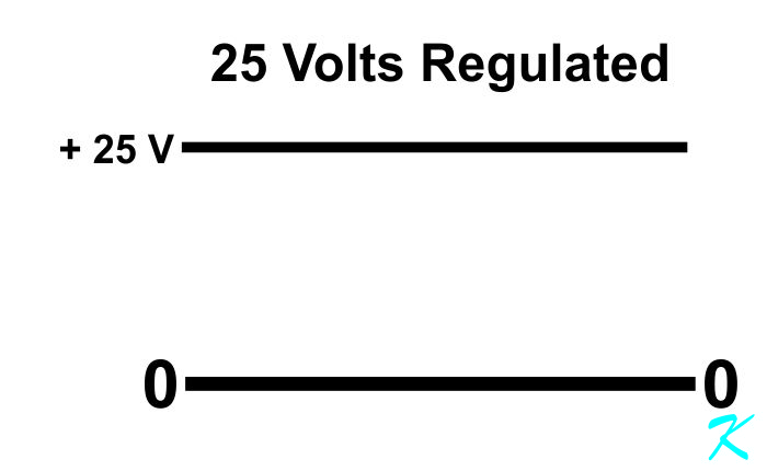
When we measure a steady, regulated 25 volts with our DC voltmeter, we are measuring a true 25 volts. A surge suppressor has a knee, which is the voltage below which the suppressor doesn't suppress the voltage. In other words, the knee has to be greater than what we measure as 25 volts DC Regulated.
But surge suppressor manufacturers can't count on that.
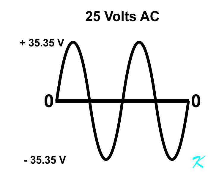
Commonly AC voltages are sinewaves, like what comes out of a 25-volt plug-in transformer. A 25-volt AC sinewave actually varies between minus 35.35 volts and plus 35.35 volts.
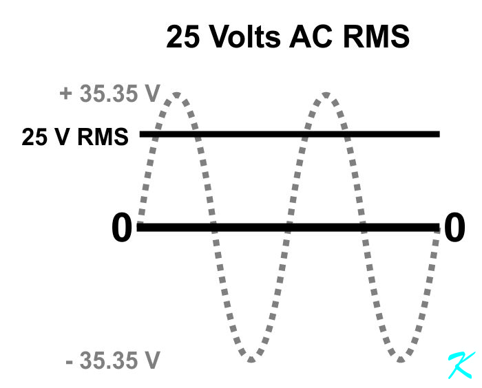
AC voltmeters, the ones carried by technicians, actually give the RMS voltage value of the AC signal. RMS is Root-Mean-Square. It's the heating value of the AC sinewave. A 25-volt DC regulated signal will provide exactly the same heat as a 25-volt AC RMS signal.
Many manufacturers of 25-volt surge suppressors take this into account, and even give a little wiggle room above that. A surge suppressor stamped with 25-volts on its side may not start suppression until the voltage actually exceeds 40 volts.
Do the Math
When working with a true sinewave AC signal, the RMS value is equal to 0.707 (1/2 of the square root of 2) times the peak voltage. Here, the peak voltage is 35.35 volts. When the 35.35 peak voltage is multiplied by 0.707, the result is 25 volts RMS.
When working with a true sinewave AC signal, the peak voltage value is equal to 1.414 (the square root of 2) times the RMS voltage. Here, the RMS voltage is 25 volts. When the 25 volts RMS is multiplied by 1.414, the result is 35.35 volts peak.
Ground Fault Sensing
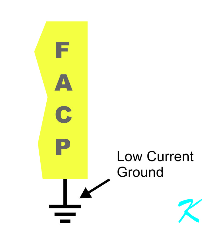
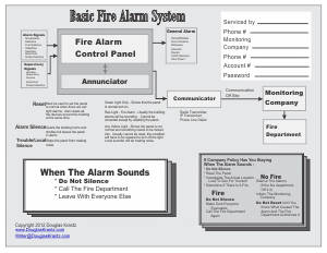
All fire alarm panels have a ground-sensing connection to ground. This is used to make sure there is no other ground connection (Ground Fault).
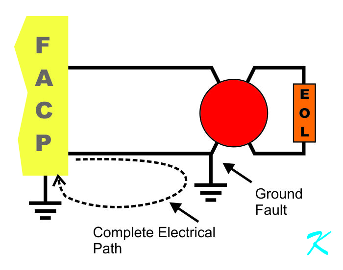
When there is a ground fault, there is a complete electrical path.
The ground fault doesn't have to be a dead short to ground, there just has to be an electrical leakage. In the specifications for each fire alarm panel is a mention of the amount of current, above which turns on the ground fault light, or the resistance, below which turns on the ground fault light.
Electrical Leakage
Whether it's an ohmmeter, a ground fault detector, or an insulation tester, the method used to find a ground fault is identical.
Douglas Krantz