How is a PCB with Mixed Lead Components Assembled?
Mixed lead components on printed circuit boards require several different soldering techniques. These techniques can include gluing the components on the boards, solder waves, solder paste, hot air, infrared radiated heat, as well as conventional soldering methods.
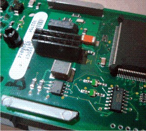
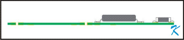
This Printed Circuit Board has Surface Mounted Devices, and it also has a through-the-hole plug inserted, making this a mixed component assembly PCB.
By Douglas Krantz
Long ago, before the Printed Circuit Board was invented, the original soldering technique consisted of hand soldering individual components using a soldering iron. That method took a lot of time to make all those connections, and produced connections that were only as consistent as the person wielding the iron.
Nowadays, using Printed Circuit Boards, wave soldering and reflow soldering is consistent from one connection to the next, and from one board to the next, making reliable and consistent electronic circuits.
PCBs With Surface-Mount Devices
Printed circuit boards (PCBs) with surface-mount devices (SMDs) can be wave or reflow soldered, while PCBs with pin-through-the-hole devices (PTHs) can only be wave soldered. PCBs with a mixture of SMDs and PTHs require both wave and reflow soldering, and have to be soldered in several steps.
Reflow Soldering
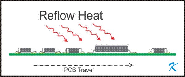
Reflow soldering requires a screen process. In the screen printing process, a paste containing both solder and flux is administered to the PCB solder pads.
In the next step, making sure the surface-mount-devices will have their leads in the paste, a machine places them on the PDB
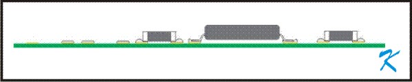
A paste, containing both solder and flux, is applied to the solder pads of the printed circuit board. The components are then placed on the PDB and the paste holds the components in place.
To solder the components to the board, a stream of hot air or radiant heat is applied to the whole board. This evenly heats up the board, the components, and the solder paste, melting the solder in the paste and connecting the components
to the board.
When all the components are placed on the PCB, heat in the form of infra-red radiant heat or hot air is used to melt the paste, which reflows to make permanent connections.
Wave Soldering
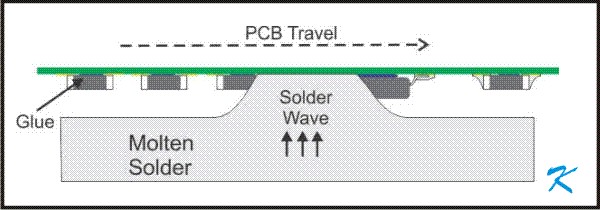
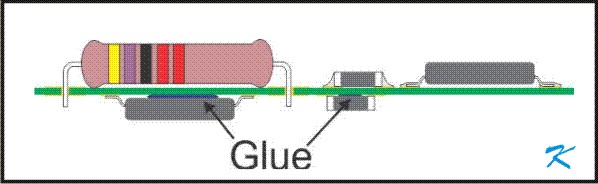
Instead of heating a paste, a solder wave can connect the Surface Mount Devices to the PCBA. However, so the Surface Mounted Devices don't fall off the PCBA as it's turned over, and the solder wave knocks off any that haven't already fallen off, the components require gluing.
PTH components cannot be reflow soldered, but require wave soldering after their leads are inserted through the holes in the PCB.
The wave of solder is produced with a pump, so that a welling up of solder will touch the PCB as it is passed over the solder-pot. All exposed metal on the bottom of the PCB will be coated with the solder.
PCBs With Both PTH and SMD Components
If PTH and SMD components are used on the PCB, more steps are required to attach them:
1. Component side SMDs are reflow soldered
Solder paste is only applied to the pads that receive components, so the other pads will remain clean for the next steps. The Surface-Mount-Devices going on the component side are placed on the PCB and the solder paste and then reflow soldered.
2. Solder side SMDs are glued in place on the solder side of the PCB.
3. Pin-Through-Hole devices are machine inserted into the holes on the PCBA
4. Hand installed devices are installed on the PCBA
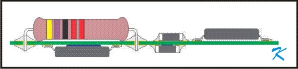
The Surface-Mount-Devices going on the solder side of the PCB are glued in place. The PDB is turned over. The other machine installed devices are insserted with their leads through the holes in the PCB. Any hand inserted devices are then installed.
5. The glued SMDs, PTHs, and the hand installed devices are soldered in one wave
The Surface-Mount-Devices going on the solder side of the PCB are glued in place. The PCB is turned over. The other machine installed devices are inserted with their leads through-the-holes of the PCB, from the component side.
6. Other components that have to be hand soldered to the PCB are then installed
7. The assembly is tested